The multi fiber fanouts are designed to divide input multi fiber cable to particular output cables or fibers with defined diameters and types of jacket. Different fanout types are designed to preserve tensile strength, environmental, mechanical and installation requirements as well as customer needs. This document is related to datasheet CON_02-03_EN-MFP_multifiber, where you can find closer info about multi fiber patch cords and also info about ordering.

MFP – Multifiber Fanout
- Designed to preserve tensile strength, environmental, mechanical and installation requirements as well as customer needs
- Multi fiber fanouts are designed to divide input multi fiber cable to particular output cables or fibers with defined diameters and types of jacket
|
FTG-XX-YY1 |
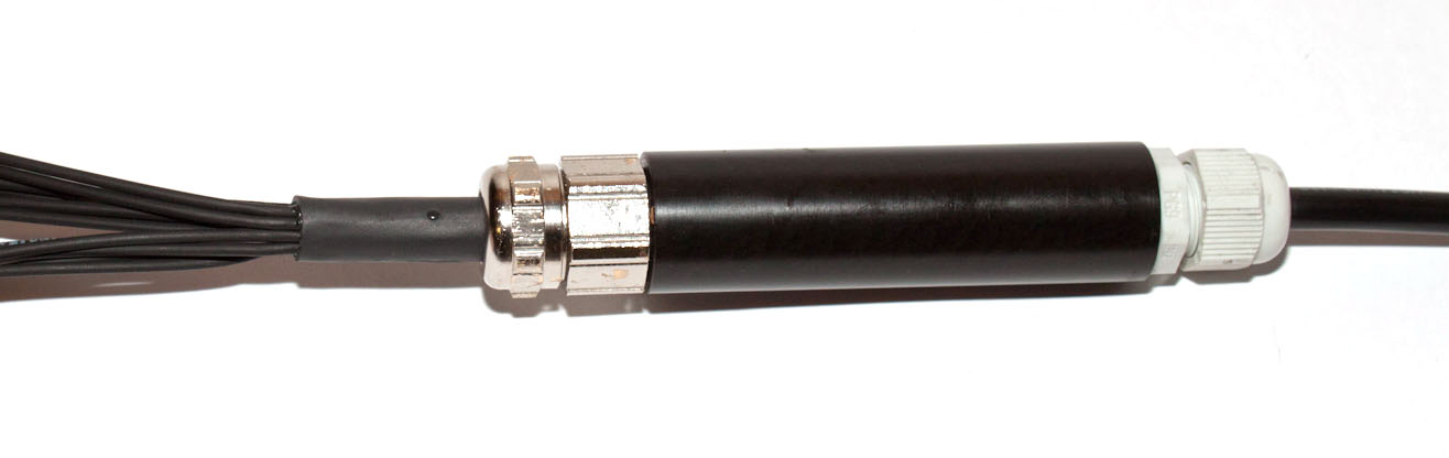
Fanout with covering tube and glands
Sign Gland Diameter range [mm] 07 Pg 7 3 – 6.5 09 Pg 9 4 – 8 11 Pg 11 5 – 10 13 Pg 13.5 6 – 12 16 Pg 16 10 – 14 21 Pg 21 13 – 18 29 Pg 29 18 – 25
|
|
|
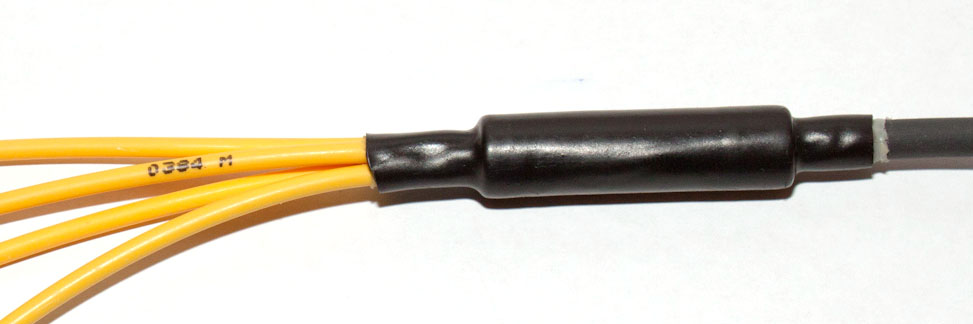
FTR-XX-YY2 |
Fanout with covering tube and heat shrink protective rubber
|
|
|
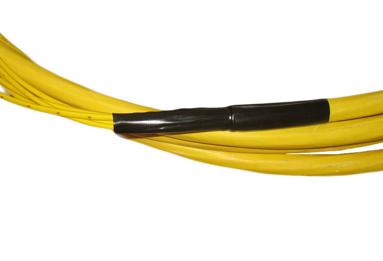
FTD-XX3 |
Fanout with durable protection tube and divided cable groups
|
|
|
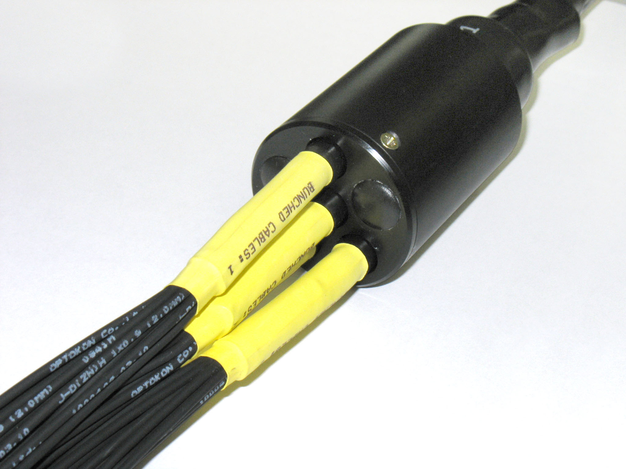
FTC4 |
Common cable splitting
connector – 100 N subcable – according cable datasheet cable – according cable datasheet |
|
|
FTF-XX4 |
Pre-fabricated fanout for bare fibers
|
|


Note:
FTG-XX-YY, please define IN-OUT gland tube, other on request
FTR-XX-YY, please define IN-OUT diameter
FTD-XX, please define group number (01 – 06), each group contain 12 cables, other configuration on request
FTC, IN and OUT diameters depends on cable type
- Telecom
- Data Centers